Prepare Infrastructure
This guide covers preparing the user-data ISO creation, accessing Local UI, and linking the edge nodes to the leader node. Follow the guide sequentially by reviewing each subsection to ensure a successful preparation of the infrastructure.
User-Data Preparation
The user-data contains the configuration for the edge nodes. The user-data is the instruction set for setting up the devices or machines that will be part of the Palette management cluster.
Follow these steps to prepare the user-data ISO. Skip to step 5 if your nodes only support a single removable media connection.
Prerequisites
-
Access to the PaletteAI ISO. Contact your Spectro Cloud representative to get access.
-
mkisofsor similar utility installed to create the ISO.
Create User-Data
-
On a machine with an ISO filesystem utility installed, create a new file called
user-data.yaml.cat > user-data << 'EOF'
#cloud-config
install:
reboot: true
poweroff: false
device: auto
grub_options:
extra_cmdline: "fips=1 selinux=0"
bind_mounts:
- /etc/lvm
- /var/lib/drbd
- /var/lib/linstor.d
- /var/lib/piraeus-datastore
- /var/lib/calico
stylus:
debug: false
trace: false
installationMode: airgap
skipStylusUpgrade: true
includeTui: true
stages:
after-reset:
- commands:
- |
sudo lvchange -an drbd-vg
sudo lvremove -f drbd-vg
sudo vgremove drbd-vg
if: "vgs drbd-vg >/dev/null 2>&1"
name: Wipe and prepare secondary SSD for CSI...
kairos-install.pre.after:
- commands:
- |
sudo lvchange -an drbd-vg
sudo lvremove -f drbd-vg
sudo vgremove drbd-vg
if: "vgs drbd-vg >/dev/null 2>&1"
name: Wipe and prepare secondary SSD for CSI...
EOFUpdate the
devicevalue to the drive to use for the Palette ISO stack, such as/dev/sda. Auto selects the largest available drive, which may not be the desired behavior, especially in multi-drive environments. If you want the appliance to power off after installation, setinstall.powerofftotrue. If you want to customize the Palette agent, check out the Edge Installer Configuration Reference page. -
Create an empty file called
meta-data.touch meta-data -
Create the user-data ISO. The following command uses the
mkisofsutility.mkisofs -output user-data.iso -volid cidata -joliet -rock user-data meta-dataExample outputTotal translation table size: 0
Total rockridge attributes bytes: 368
Total directory bytes: 0
Path table size(bytes): 10
Max brk space used 0
182 extents written (0 MB) -
Load the user-data ISO onto a bootable device, such as a USB drive, or upload the ISO to a datastore in your VMware environment. You can use several software tools to create a bootable USB drive, such as balenaEtcher.
For VMware vSphere, you can upload the user-data ISO to a datastore using the vSphere Client or the govc CLI tool. Refer to the vSphere or govc documentation for more information. For bare metal, you can use tools like scp or rsync to transfer the user-data ISO to the nodes, or use a USB drive to boot the nodes from the ISO.
Ensure that the user-data ISO is accessible to all nodes that will be part of the Palette management cluster.
-
Upload the PaletteAI ISO to your infrastructure provider. This can be done using the web interface of your infrastructure provider or using command-line tools. Ensure that the PaletteAI ISO is accessible to all nodes that will be part of the Palette management cluster.
This concludes the user-data preparation. The next step is to prepare for booting up the nodes from the ISO and accessing Local UI.
Validation
-
Validate both the user-data ISO and the PaletteAI ISO uploaded to your infrastructure provider. If you created an ISO using physical media, validate that the PaletteAI ISO is bootable.
-
Verify the user-data settings are correct. More importantly, verify the
install.devicevalue is correct and matches the drive you want to use for the Palette ISO stack. Typically, this is/dev/sda.
Boot Up and Access Local UI
The next set of steps assumes that you have completed the User Data Preparation section and that each node meets the Hardware Requirements specified in the Overview and Prerequisites sections.
Prerequisites
-
Completed the User-Data Preparation section.
-
At least six devices or machines available that meet the Hardware Requirements specified in the overview and prerequisites section.
-
Network connectivity to the devices that will be part of the Palette management cluster and the ability to access Local UI.
-
At least six IP addresses available for the nodes that will be part of the Palette management cluster. You can configure these IP addresses during the cluster creation steps in Local UI.
-
A web browser to access Local UI on port 5080.
Boot Up
-
Attach the PaletteAI ISO and the user-data ISO to the nodes and ensure the boot order is set to boot from the PaletteAI ISO first.
warningIf your nodes only support a single removable media connection, attach the PaletteAI ISO only.
For example, in VMware vSphere, the VMs will have the PaletteAI ISO in CD/DVD drive 1 and the user-data ISO in CD/DVD drive 2. Refer to the documentation of your infrastructure provider for specific instructions on how to attach and boot from multiple ISOs.
-
Power on the nodes. The boot-up process may take 30 minutes or more. If you set
install.powerofftofalsein your user-data file, the nodes will restart automatically once the Palette agent is installed. The following image shows the nodes booting up and copying content to the disk.
-
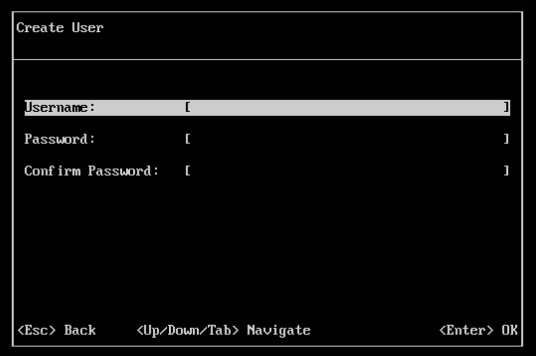
Wait for each node to display the Terminal User Interface (TUI). The TUI allows you to configure a system user, password, and network. The username and password are used to access Local UI. Press ENTER when the TUI is displayed to create a username and password. Press ENTER again when finished.
-
Once your login credentials are set, the left menu displays several networking categories. Use the TAB key or the up and down arrow keys to navigate between menu items. Press ENTER to select a menu item and subsequent fields. Make any necessary changes, and press ENTER again to apply them. Press ESC to return to the left main menu.
infoNetwork proxy is configured in Local UI. In the next section, Link Edge Nodes to Leader Node, you can use that opportunity to configure the network proxy for the Edge nodes.
-
After you are satisfied with your TUI configurations, from the left main menu, select Logout, and press ENTER to complete the configuration. Note the Local UI console address. This is the IP address and port used to access the node's Local UI.
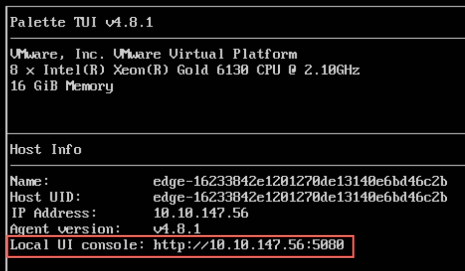
-
Open a web browser and navigate to the Local UI console IP address and port. Log in with the system user and password configured in the TUI.

-
Repeat this process for each edge host.
This concludes the boot up and access Local UI. The next step is to link the Edge nodes to the leader node.
Link Edge Nodes to Leader Node
The next set of steps assumes you have completed the Boot Up and Access Local UI section and that each node meets the Hardware Requirements specified in the Overview and Prerequisites sections.
Prerequisites
-
Completed the Boot Up and Access Local UI section.
-
Network connectivity to the devices that will be part of the Palette management cluster and the ability to access the Local UI.
-
A web browser to access Local UI on port
5080.
Link Edge Nodes to Leader Node
-
Pick one of the Edge nodes and navigate to Local UI. Use the IP address of the Edge node and port
5080to access the Local UI. For example, if the IP address of the Edge node is10.10.10.10, Local UI will be accessible athttps://10.10.10.10:5080. -
From the left main menu, select Linked Edge Hosts.
-
Select Generate token. The host begins generating tokens that you will use to link this host with other hosts. The Base64 encoded token contains the IP address of the host, as well as a One-Time Password (OTP) that expires in two minutes. Once a token expires, the leader generates another token automatically.
-
Select the Copy button to copy the token.

-
Log in to Local UI on another host that you want to link to the leader host.
-
From the left main menu, select Linked Edge Hosts > Link this device to another.

-
In the pop-up box that appears, paste the token you copied from the leader host.
-
Confirm the link.
-
Repeat steps 5-9 for every host you want to link to the leader host.
-
(Network proxy only) If you are using a network proxy, you must consider the proxy on each edge node. From the left main menu, select Edge Host and navigate to the Proxy section. Select the Edit icon, and complete the fields in the Edit Proxy Configuration drawer. Confirm your changes when finished.
Validation
-
Log in to Local UI on the leader host.
-
Verify all the edge nodes are linked to the leader node. Navigate to the Linked Edge Hosts page and verify all the edge nodes are listed.
Next Steps
At this point, your infrastructure is prepared, and you may begin the configuration of the Helm chart values. Proceed to the Prepare Helm Chart Values section.